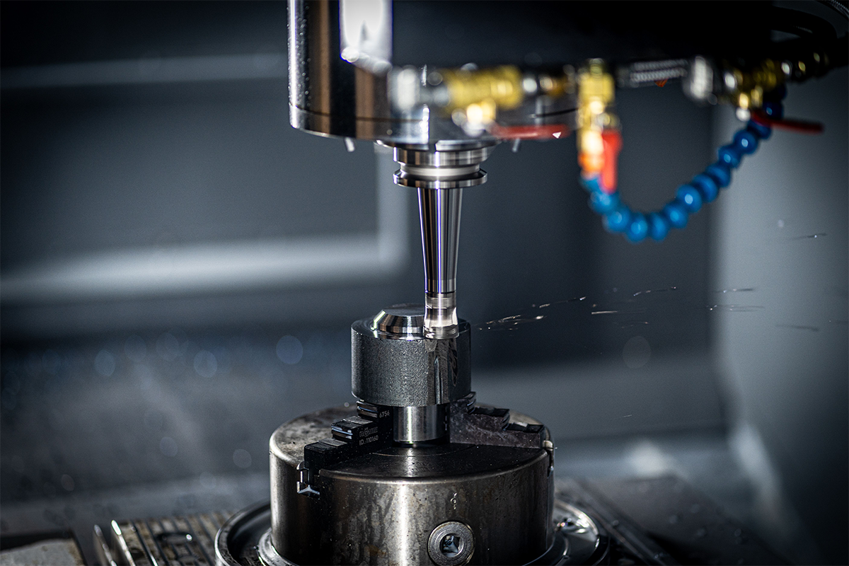
CNC Milling Tolerances: Use Precision Where It Matters
Modern CNC milling machines can position very accurately, but machine accuracy and finished-part accuracy are not the same thing. The tolerance that can be held on a real part depends on feature size, material, cutter diameter, tool length, workholding rigidity, temperature, setup count and inspection method.
A simple aluminum component machined with short tools and rigid clamping may hold a tight tolerance more consistently than a deep stainless steel part that requires long-reach tooling. For this reason, tight tolerances should be reserved for functional features such as bearing bores, locating holes, mating surfaces, seal interfaces and critical hole patterns.
Over-tolerancing non-critical dimensions usually increases machining and inspection time without improving part performance. When reviewing a drawing, ask what will happen if a dimension moves slightly within a wider range. If the answer is that assembly and function are unaffected, the tolerance may be tighter than necessary.
Dimensional Tolerances and GD&T
For complex milled parts, GD&T can communicate functional requirements more clearly than several tightly controlled plus-or-minus dimensions. Common controls include flatness, parallelism, perpendicularity, position and profile. A positional tolerance, for example, may describe the functional relationship of a hole pattern more effectively than separate X and Y dimensions.
Datum selection becomes especially important when a part is machined from multiple sides. Critical features should be referenced to functional datums that can also be established consistently during manufacturing and inspection.
CNC Milling Surface Finish: Choose the Right Ra
Surface finish should be specified according to function, not simply appearance. A smoother surface can require additional finishing passes, lower feed rates, fresher tooling or secondary operations. Typical machined requirements may include Ra 3.2 μm for general surfaces, Ra 1.6 μm for more precise mating surfaces and Ra 0.8 μm for demanding sealing or sliding areas, although the correct value depends on the application.
Surface roughness and dimensional accuracy are different requirements. A part can be dimensionally correct while still showing visible cutter marks, and a polished surface can look excellent while a dimension is out of tolerance. Poor finish may result from tool wear, runout, chatter, excessive tool stick-out, weak workholding or flexible features.
Internal Corners and Deep Pockets
Internal corner radius is one of the most important CNC milling design choices because a round end mill cannot create a perfectly sharp internal corner. Smaller radii normally require smaller cutters, and smaller cutters are less rigid and remove material more slowly. The effect becomes more severe when the corner is also deep.
Whenever possible, design the internal radius larger than the cutter radius instead of matching it exactly. Extra clearance allows the tool to move through the corner with smoother engagement, reducing cutting force, chatter and tool wear.
Deep pockets create a similar problem. As pocket depth increases, the cutter must extend farther from the holder. Longer tool stick-out reduces rigidity and increases the risk of deflection, chatter, poor surface finish and dimensional variation. If a deep cavity is necessary, increasing pocket width or corner radius may allow a larger, stiffer tool to be used.
Another useful design rule is to separate functional requirements from manufacturing preferences. If a pocket only needs clearance, its floor depth, corner radius and wall angle often have more flexibility than a sealing face or bearing feature. Giving the supplier room to select an efficient cutter can shorten cycle time without changing how the part works. The same idea applies to holes, slots and edge breaks: standard sizes and accessible geometry are usually easier to machine, inspect and reproduce than custom dimensions that provide no functional benefit.
Tool Access, Thin Walls and Tool Deflection
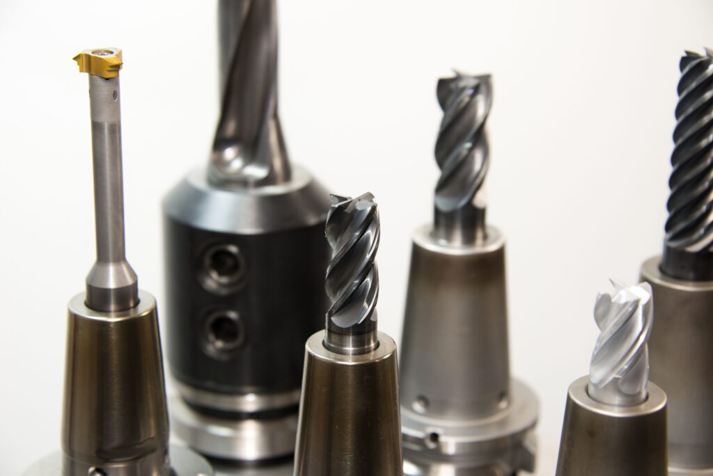
A feature may be valid in CAD but difficult to reach with a real cutting tool. Deep narrow cavities, side features, recessed slots, undercuts and surfaces hidden behind tall walls can require special tooling, additional setups or a different machine. Improving access from the design stage can reduce both risk and cost.
Thin walls are also sensitive to cutting forces. A tall or flexible wall may bend while being machined and spring back after the cutter passes, causing taper, thickness variation, chatter or distortion. There is no single minimum wall thickness that works for every part because stability depends on wall height, material stiffness, toolpath, support and required tolerance.
Tool deflection follows the same principle. Small-diameter cutters and long tool reach increase bending under cutting load. Engineers can reduce this risk by increasing internal radii, avoiding unnecessarily narrow slots, reducing pocket depth and allowing larger tools wherever the design permits.
CNC Workholding and Multiple Setups
Every milled part must be located, supported and clamped securely. Parts with flat, accessible surfaces are generally easier to hold than parts with thin bases, complex contours or no parallel clamping faces. Difficult geometry may require soft jaws or custom fixtures, which adds preparation time and cost, especially for prototypes and low-volume production.
Multiple setups can also affect accuracy. When a part is flipped or repositioned, a small location error may be introduced. If two critical features are produced in different setups, their relationship may be harder to control than if both are machined from the same orientation. Where possible, design related precision features so they can be completed in one setup and referenced from the same datum system.
3-Axis vs 5-Axis CNC Milling
More machine axes do not automatically mean a better process. For plates, brackets, housings and many prismatic components, 3-axis milling is often the most economical option. Five-axis machining becomes more valuable when a part has compound angles, features on several sides, complex contours or tight relationships between features that would otherwise require repeated repositioning.
Although a 5-axis machine may have a higher hourly rate, it can reduce setup time, fixture requirements and repositioning error. The right choice should be based on total manufacturing efficiency rather than machine rate alone.
Speeds, Feeds and CNC Milling Chatter
Cutting performance depends on spindle speed, feed rate, chip load, depth of cut, cutter geometry, material and machine rigidity. Mechanical engineers normally do not need to specify these values on the part drawing. The drawing should define material, dimensions, tolerances, GD&T, surface finish, threads and inspection requirements, while the machining supplier selects cutting parameters for the actual machine and tool.
Chatter is an unstable vibration between the tool and workpiece. It can cause visible marks, poor finish, dimensional variation and reduced tool life. Deep pockets, thin walls, long tools and small internal corners all increase the chance of chatter because they reduce system rigidity. Many chatter problems can therefore be prevented at the design stage rather than corrected only by changing machining parameters.
What Makes a CNC Milled Part Expensive?
CNC milling cost is driven by more than material price and machine hourly rate. The largest contributors are usually machining time, setup count, tight tolerances, deep features, small internal radii, demanding surface finishes and difficult-to-machine materials.
Large amounts of material removal and complex 3D surfaces increase cycle time. Additional setups require alignment and verification and may need custom fixtures. Tight tolerances can add slower finishing passes, extra inspection, CMM measurement and greater scrap risk. Small internal radii and deep pockets may force the use of smaller or longer cutters, which reduce productivity.
Material also matters. Aluminum is generally easier to machine than stainless steel or titanium, while tougher materials increase cutting forces, tool wear and cycle time. In many cases, the most effective way to reduce cost is not to negotiate a lower machine rate, but to simplify the design before production.
CNC Milling DFM Checklist for Mechanical Engineers
Before releasing a part for quotation, check whether tight tolerances are limited to functional features, datums are clearly defined, internal radii are large enough, pockets are no deeper than necessary and tools can physically reach every feature. Also review thin walls, clamping surfaces, setup count, surface finish requirements, standard hole and thread sizes, and whether critical dimensions can be inspected easily.
A short DFM review at this stage can identify manufacturing risks before they become expensive production problems.
Design for Function, Then for Machinability
Good CNC milling design balances function, tolerance, tool access, rigidity, workholding, surface quality, inspection and cost. Small changes such as increasing an internal radius, reducing unnecessary pocket depth or relaxing a non-critical tolerance can allow larger tools, fewer setups and more stable cutting conditions.
At Yiling CNC, we manufacture custom CNC metal parts from customer 2D drawings and 3D models. If you are developing a new component and want feedback on tolerances, tool access, material selection or machining feasibility, send us your drawing for a DFM review and quotation.